


ROUGH DRAFT - FINAL OVERVEIW STILL IN DEVELOPMENT
------------ Getting Started---------
Not Included
- Container(s)
- water pump
- PCM or bilge pump controller (highly recommended but not absolutely necessary)
- 2 liter plastic soda bottles
- minus 8 mesh material (up to -4 mesh*)
-------------- Container setup -------------
-Easiest setup
The simplest container setup up would just be a small container inside of a larger container. Both containers would be full of water, the bilge pump would reside in the larger container and the waste material will build up in the small container, making clean up easier. The smaller container will be shorter than the larger one so that the water in the small container will over flow into the larger one.
-Multi container setup
In addition to the previous setup, another small container can be added into the large container. This second smaller container will hold the bilge pump that will then be connected to the other small container through a siphon pipe. The siphon pipe is recommended to be at least 1 1/2" ID or larger depending on flow rate requirements. This setup requires less water so that the large container doesn’t need to be filled up but the water from the waste container will overflow into the large one once it becomes full of material. This is the set up I use the most when testing the feeder, it allows me to remove material straight from the waste container into the hopper repeatedly without having to clean up each time. The next setup addresses the issue of water conservation incase it is desired during operation.
-Water recovery setup
Building off of the last setup, we can add a third small container that will capture the water overflowing from the waste container. This container will have a small cup of water suspended near the top lip of the third container. The water level in this small cup must be slightly lower than the lip of the container, and must have a path to overflow into the small container it rests in. From there, the small cup and bilge pump container will be connected through a siphon tube (1/2" tubing is sufficient for most applications). Through that all 3 small containers will be connected through a siphon and when anyone reaches above the overflow level of the small cup, the cup will begin to overflow and fill up the container it rests in. This setup is good for small apartment use or maybe for desert prospecting where water is scarce. This setup is also great for testing gold traps, once the waste container is full, it can be swapped out with another container. Next you empty the overflow container back into the waste container and then you can reprocess the material without having to transfer it to another container.
------------ Siphon Feeder Setup------------
-Feeder ports overview
1. Water inlet port - from bilge pump or water pump
2. Hopper Port - reservoir attachment point
3. Classifier port - discharge of classified materials
4. Main outlet port - Discharge of all/heavy materials
-Pump to water inlet port
Provided are 3 sizes of tubing that are able to connect together. For the standard set up of the micro feeder I recommend starting with the following supply tube setup. Starting with the largest size, cut a section about 3 inches long. Find the tube that is one size smaller and cut a piece an inch or more longer. Last locate the smallest size tubing and insert it into the next larger tubing. Then insert that into the largest tube that will then connect to the water inlet port of the feeder. Once that is together run the smallest tube into a pump, each pump is different so you may have to try different things to hook some pumps up. Make sure water inlet tube is long enough to allow the feeder to pivot freely, this can be cut to the desired length if it is to long.
-Hopper port
The hopper port on the micro feeder is designed as a male connector to a plastic soda bottle. Like a 2 liter bottle that is turned upside with the hopper port going into the opening of the bottle. From that view point the bottle would be cut off a little less than half way down so that material can be fed into the top. For the micro I recommend a little less than half a bottle so that the hopper doesn’t become overloaded with material, potentially causing the device to break.
-Classifier port
The classifier port connects to the 1/2" tubing but also gets reduced twice. However this time the 1/2" tubing must around 3" above port and the reduction point around 2" inches above the port. This creates a turbulent drop out zone within the 2" of the 1/2" tubing, that allows larger gravels to fall down while still siphoning the smaller lighter particles up. Reducing the classifier outlet twice makes it easier when separating the finest material and reducing it once helps when separating slightly larger particles.
-Main outlet port
This port is pretty straight forward, this is where all your heavier material will go and where all the material will go when the classifier is not in use.
It uses the same 1/2" tubing as the rest but it doesn’t have to be reduced all the time, in fact the large tube acts as a turbulent drop out zone for gold that seems to stick good to the vinyl. However if the gold is to large it will actually build up enough to back the system up. To fix that you would just reduce the main outlet tube one time to the smaller tube. This will give the outlet tube roughly the same inside diameter as the feeder, that’s creates more of a laminar flow and makes it hard for anything to build up, even gold.
-Gold Traps
From there each outlet tube will be fed to individual gold traps, the classifier tube can be fed into a trap specialized for fine material, while the main outlet feeds into a stronger more turbulent trap. I have tried several interesting looking gold traps but I find that a simple DIY set up can catch a lot while being fed at a fast rate. Imagine the end point of the outlet tube, coming from it is a mixture of dirt/gravels and water. If this mixture were allowed to drop into a small cup, gold would drop out and get trapped in the cup, while everything gets flushed out. That is just a most basic idea of a usable gold trap for this system that can be very effective. But I strongly encourage you to experiment and think of different ways of trapping gold, it can be a lot of fun.
---------- Feeder stand setup ----------
The feeder stand comes mostly prebuilt but some assembly may be required. It is set up to wrap around the outside bottom of a small container allowing the feeder to hang over into the container. This is usually the water pump container I spoke of in the container setups section. All fittings are left unglued so that the stand can be reconfigured for different situations, the stand can be glued all together if desired but isn’t usually necessary.
--------- Outlet tube support stand-----
This stand is a simple configuration to hold each tube at different heights and that allows the adjustment of at least one tube. This can be setup a dozen different ways, so I just provide a simple out of the box solution for this stand but it will need to be reconfigured when trying other gold traps and accessories.
DETAILED OVERVIEW
Basics of functions come down to turbulent vs laminar flow
The feeders, of the Siphon Sluice Line up, will automatically feed material into a gold trap at a controlled rate and uses a hopper that is filled with material to be processed. In addition all feeders have a classifier port built in that aids in the recovery of fine gold. The Siphon Sluice feeder design is scalable and each version is built off the same concept with some details changed with each size.
The Micro feeder
This is the smallest version of the siphon sluice feeder, it runs best with -8 mesh material but could run up to -4 mesh depending on make up of the material being used. It has the slowest potential feed rate out of the other versions but it is also more plug and play than the other versions. This was designed to be as affordable and as entry level as possible, because of this the hopper cant be to big or heavy. Aside from the lower feed rate, small mesh requirements and a reduced hopper size, the micro feeder is a great entry level device that is actually affordable and is a fun device to play around with. It can also be great in helping with cleaning up concentrates.
The Mini feeder
This version of the feeder takes a little more time to produce but it comes with some added benefits over the micro version. This version can easily handle -4 mesh material with a really high potential feed rate. It comes with dual supports to handle a larger hopper and therefor can be adapted to attach a small bucket, allowing higher volumes of material to be processed automatically. Furthermore this version of the feeder comes reinforced at all its weak points, that on top of the other additions make this version good for in field use as an alternative for panning or using a small river sluice.
Micro feeder
- sub 8 mesh (and up to sub 4 mesh*)
- slower feed rate vs mini
- 1/2" vinyl connection ports
- 1/2" PVC support coupling
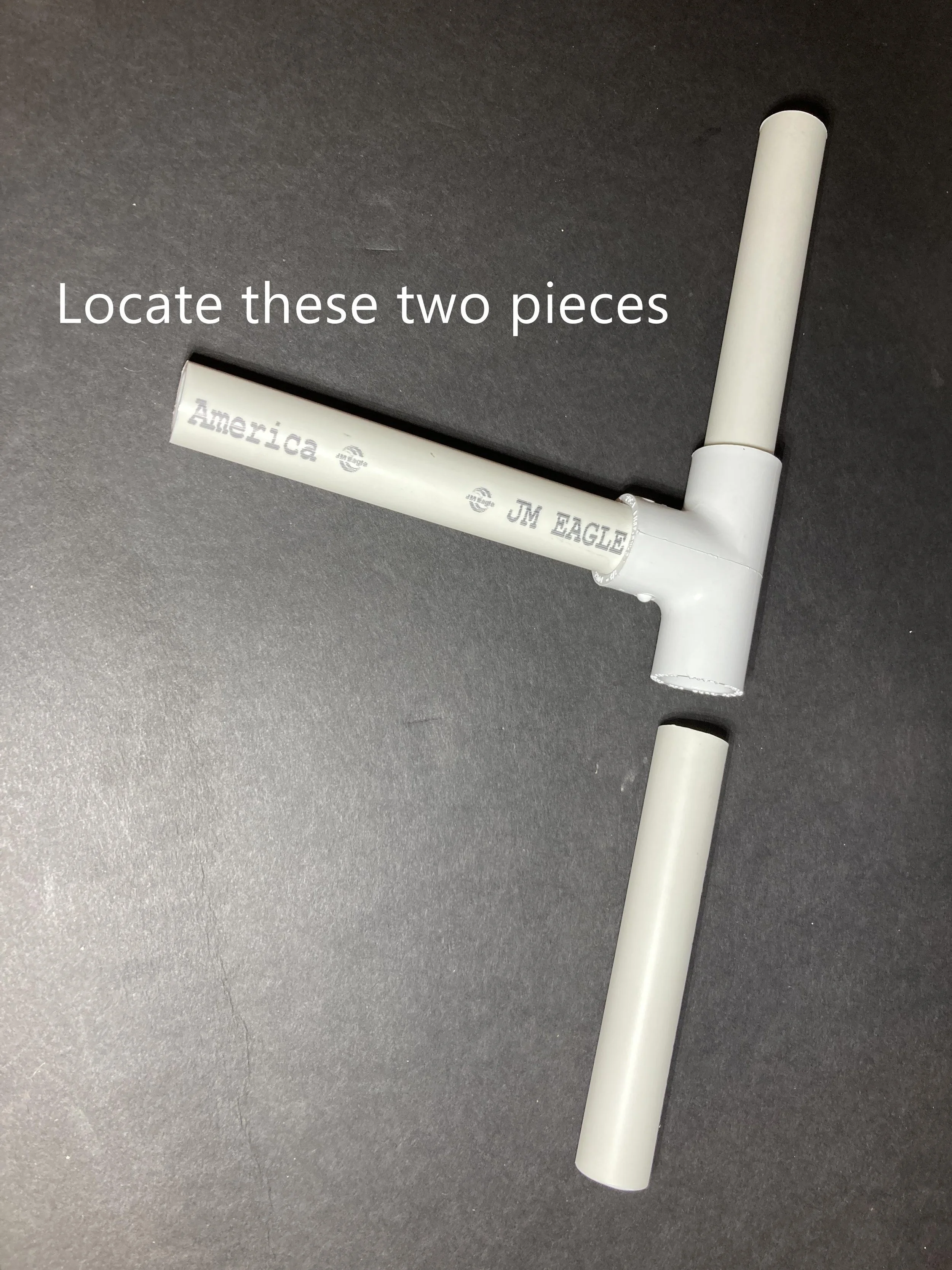
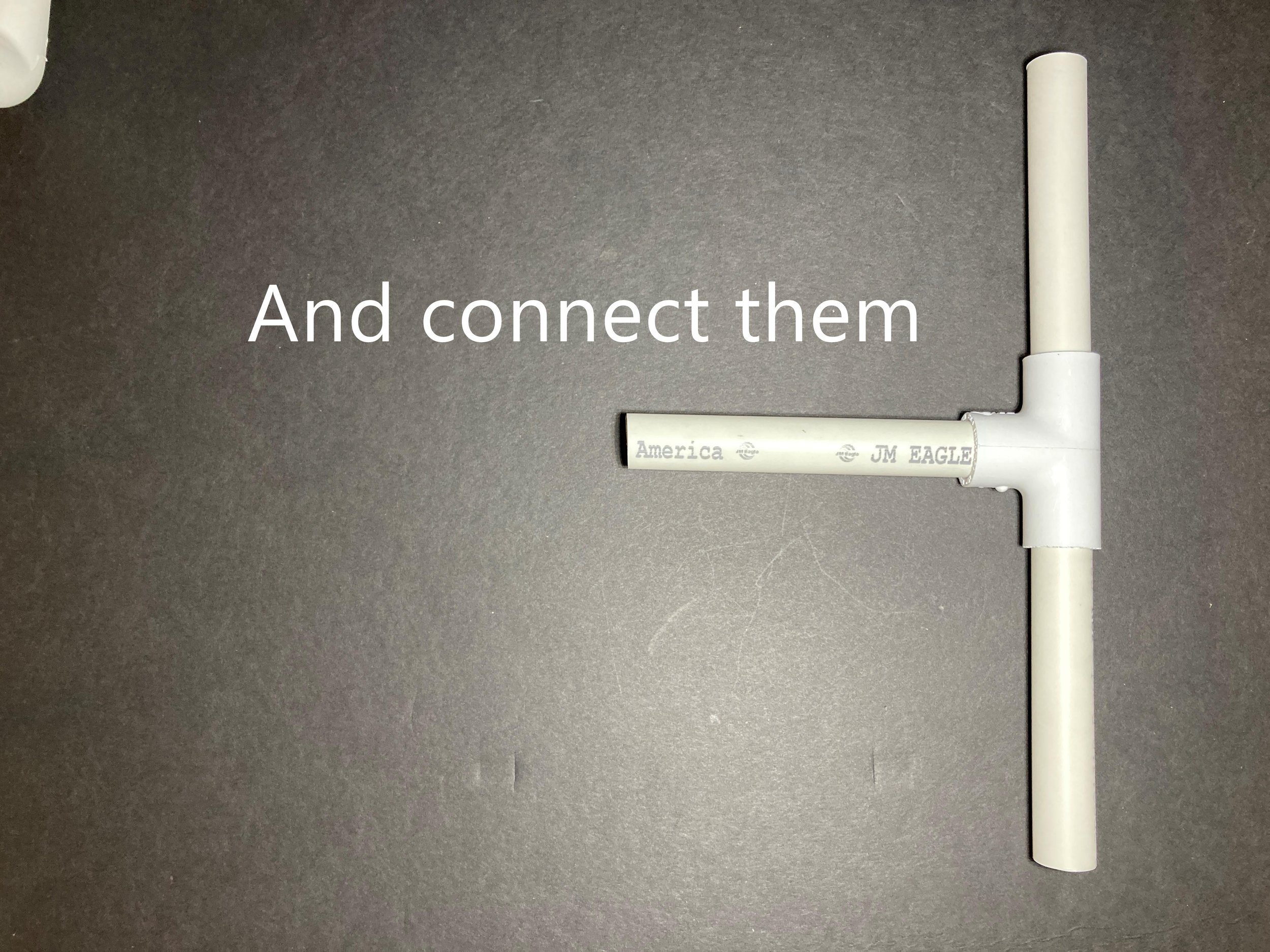
Support
- Support stand is made of 1/2" PVC pipe and fittings
- Support on device is 1/2" coupling made to accept 1/2" PVC pipe with a small bit of resistant.
- Device support coupling is made so that the entire feeder can pivot in order to control the feed rate, a small amount of resistance in the support coupling allows the feeder to stay in place when it is pivoted.
- The "feed rate controller" was designed this way so that nothing mechanical comes into contact with the material, thereby creating a more rugged and reliable device with less potential errors.
- The micro feeder is only supported on one side because it is only designed for a small hopper, this among other details allow the micro to be the easiest device to use and the cheapest in the siphon sluice lineup.( the mini feeder is supported on both sides so that a small bucket can be adapted to it for higher volume of material processing with less effort)
Feeder stand
- The pre built stand that is included is just a basic out of the box setup that can be used with a setup that uses small containers. If 5 gallon buckets or something else is being used as containers then the stands can be reconfigured for each situation. The stand does not come glued together and generally doesn’t need to be, but it can be glued together if desired.
- It is best that the support PVC fitting be right up against the feeder, so that the small piece of PVC pipe cant be seen once the feeder is installed on it. If the small PVC were to long, it may create excessive leverage force and could break the support coupling on the feeder. This may not a big concern with the micro but it is definitely not recommended for the mini feeder. So as a safe rule it is best to keep the support PVC tube as short as possible.
Bilge pump to inlet port connection
- A PCM or bilge pump controller is highly recommended to make using this system easier but isn’t absolutely necessary
- The required flow rate is very low but varies depending on which functions are being used. less than 200 GPH should be enough when using both outlets at max flow, the lowest required GPH flow rate is about 80 and that is when the classifying port is not being used and the main port being used with the lowest possible flow rate.
- 1/2" vinyl tubing is reduced twice that runs to the feeder,
where it is then ran back into 1/2" vinyl to connect to the inlet.
- Reducing the inlet helps with the feeding and classification functions, but this is one
point that can be experimented with to produce different results, i.e. reducing the vinyl once instead of twice.
- The overall length of the water inlet tube must be long enough to allow the feeder to pivot freely.
Hopper
- The mini feeder hopper port uses a soda botte for the reservoir, like an upside down 2 liter plastic bottle etc.
- The hopper port of the micro feeder will go inside of the plastic bottle hole.
- The mini feeder is only supported on one side and is not meant for a lot of weight, Less than half of a 2 liter
bottle full of material should be a safe load on this device.
- as long as a layer of water remains above the material in the hopper, the material will continue to drain all the way. When the material Contains less sands and more gravels, a small amount of water can be fed into the top of the hopper to aid in feeding the material.
Main exit port
- This is the main port where the heavier material falls out and flows into a gold trap, and where all the materials goes when the classifier isn’t being used.
- The 1/2" vinyl tubing can be ran from this port. When using the 1/2" tube only, some larger gold will fall out and get trapped in the tube. If that is not desired then the 1/2" can be reduced once to keep it clear of gold.
Classifier Port
- Reducing this tubing only once will produce different results, like higher feed rates and different meshes of classification.
- The end height of each tube relative to one another will determine the level of classification. So that when the classifier tube is of equal height or higher than the main tube, the siphon will be weaker and thus only sucks up the lightest material. When the classifier tube is below the height of the main tube, the siphon is stronger and only the biggest gravels of the material fall into the main outlet. This is based off of the classifier tube being reduced once. When this tube is reduced twice like mentioned above, the height of the classifier tube can below that of the main tube without it sucking up the larger gravels.
Feed Rate Control
- There are several ways to control the feed rate. The two main ways are by pivoting the feeder and changing the flow rate of water into the device. The flow rate will almost always be very low, just enough to maintain about an inch or so of standing water above the hopper port. Generally lower flow rates produce higher feed rates, but if the flow rate is to low, the main tube could become clogged or could begin to suck in air from the hopper port which would break down the function of the classifier tube, if it is being used. In addition lower flow rates may require adding water more often to the hopper. The third thing to change is the end heights of outlet tubes relative to the height of the hopper port, when the end tube height and hopper port height are the same, max feed rate can be achieved, but if the main tube end is lower than the port than a higher flow rate is required to stop air from being sucked into the hopper port. Also the feed rates will always be higher when the classifying port is being used. Without using the classifying port, the highest feed rates can be achieved by pivoting the feeder all the way forward and turning the water pump to the lowest possible setting without the main tube getting clogged. This all changes slightly when using inline gold traps but the basic ideas remain the same.